Setup
Navigation:
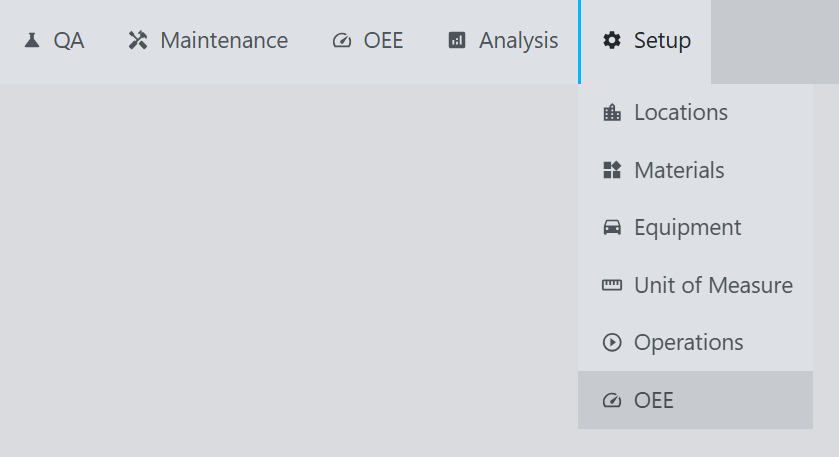
Example:
Description:
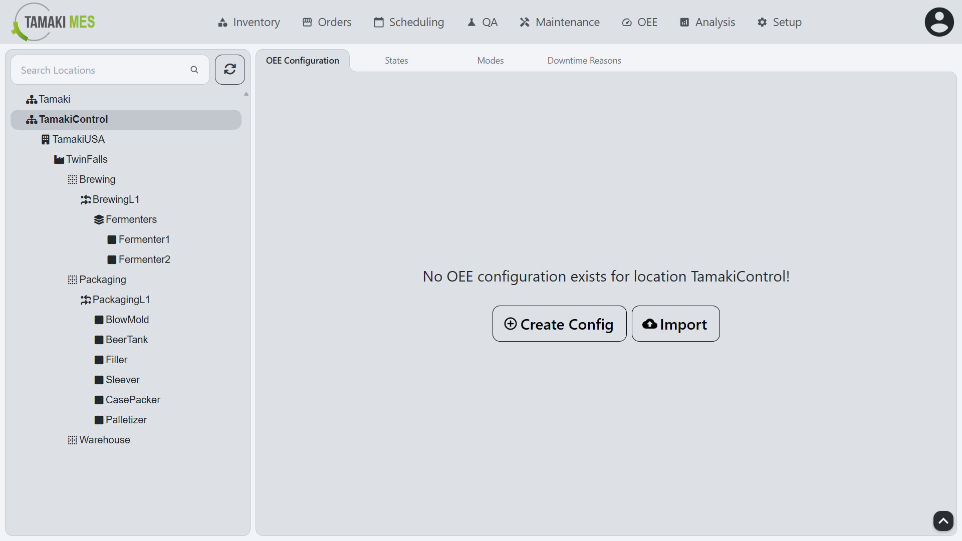
- The Setup screen allows users to configure the OEE model, including defining States, Modes, Downtime Reasons, and other OEE Configurations. This screen is essential for customizing the OEE tracking system to fit the specific needs of the manufacturing operation.
How to use:
- To populate the OEE Configurations, States, Modes, and Downtime Reasons tabs, the user must first select a location from the location tree on the left side of the screen. This selection will determine which configurations are displayed and modified.
OEE Configuration
Example:
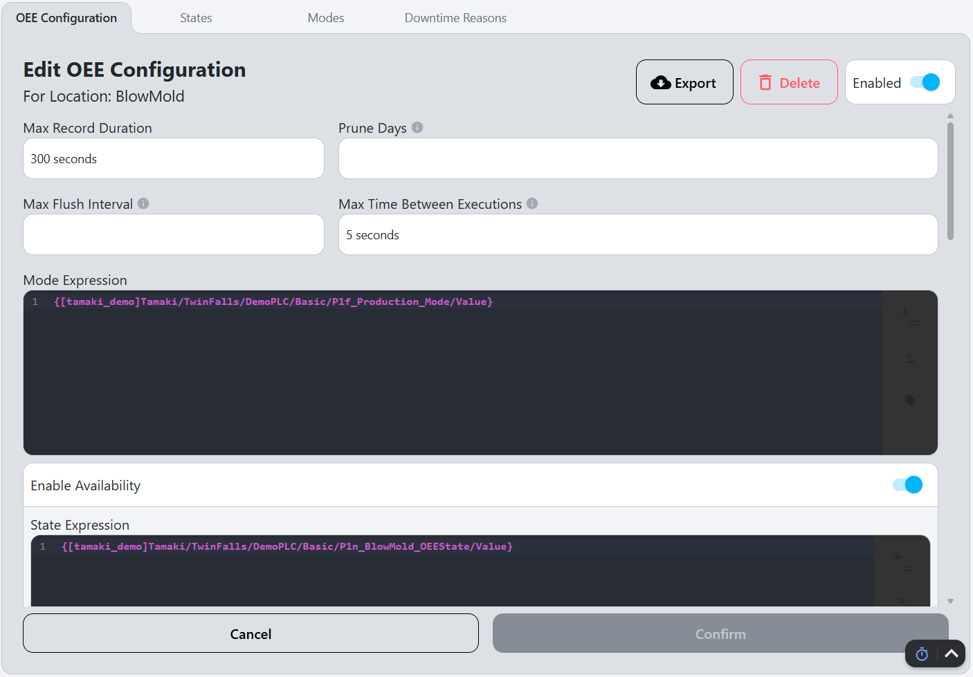
OEE Configuration Workflow
- Select a location from the dropdown menu to configure OEE settings for that specific location.
- Set the Max Record Duration and Prune Days.
- Set the Max Flush Interval and the Max Time Between Executions.
- Fill out the Mode Expression.
- Configure the Availability settings:
- Enable Availability.
- Fill out the State Expression.
- Configure the Downtime Reason Source and Downtime Reason Expression.
- Configure the Performance settings:
- Enable Performance.
- Fill out the Production Count Unit of Measure.
- Fill out the Production Rate Time Unit.
- Fill out the Production Count Expression.
- Set the Production Count Overflow Value.
- Configure the Standard Rate Source and set the Standard Rate.
- Configure the Quality settings:
- Enable Quality.
- Fill out the Waste Count Expression.
- Set the Waste Count Overflow Value.
- Configure the Production Order Source.
- Save the configuration by clicking the
Confirmbutton at the bottom of the screen.
OEE Configuration Fields
Export
Exports the OEE configuration for the selected location to an Excel file. This can be useful for backup purposes or for transferring configurations between different instances of Tamaki MES.
Delete
Deletes the OEE configuration for the selected location. This will not affect any existing OEE Records at this location, they will remain.
Enabled
Toggles the OEE tracking for the selected location.
Max Record Duration
Maximum duration for an OEE record in seconds. Normally, the following events cause an OEE record to cut over to the next record:
- OEE Mode change at the location.
- Standard rate change at the location.
- Production order change at the location.
- [future] Operation start or end at the location.
- [future] Shift start or end at the location.
If none of those events occur within the Max Record Duration, the OEE record will to cut over to the next record automatically. The purpose of this is to control the granularity of the records. Changing this value will not affect existing records, but will apply to new records created after the change.
Prune Days
Number of days to retain OEE records in the database before deleting. (If blank, records will be kept indefinitely)
Max Flush Interval
Maximum time oee data being flushed into the database from the data collection service.
Max Time Between Executions
Maximum number of seconds between data collection evaluating data.
Mode Expression
The Expression Field is evaluated to an integer value corresponding to a Mode's code of the location is bound to the OEE model.
Availability
Enable Availability
Enables availability tracking for the OEE Records. This allows the system to track when the location is running and when it is not, providing insights into the operational efficiency of the equipment.
State Expression
This is where the Oee State's code number is specified for this location State. This can be a static value but will most likely be a tag binding to reflect the PLC's value for the state of the machine Expression Field.
Downtime Reason Source
Opens a dropdown with the following options:
- Manual: The downtime reason will be manually selected by the user when a downtime event occurs using the Downtime Entry page.
- Expression: The downtime reason will be determined by the Downtime Reason Expression field.
Downtime Reason Expression
This is where the Downtime Reason's fault code is specified for this location Downtime Reason. This can be a static value but will most likely be a tag binding to reflect the PLC's value for the fault code of the machine Expression Field.
Performance
Enable Performance
Enables performance tracking for the OEE Records. This allows the system to track the production count and rate of the location.
Production Count Unit of Measure
The unit of measure for the Production Count. This is used to define how the production count is measured, such as in pieces, kilograms, or liters.
Production Rate Time Unit
The time unit for the production rate, such as seconds, minutes, or hours. This is used to define how the production rate is calculated.
For example, if this field is set to Minutes, and the Production Count Unit of Measure is set to Pound, then the production rate will be calculated in Pounds per Minute.
Production Count Expression
This is where the production count value is specified for the location Production Count. This can be a static value but will most likely be a tag binding to reflect the PLC's value for the current production count at the machine Expression Field.
Production Count Overflow Value
The tag capturing production count will roll over to 0 when it reaches this value. This is used to calculate the production count.
Standard Rate Source
Opens a dropdown with the following options:
- Static: The standard rate will be a fixed value set in the Standard Rate field.
- Expression: The standard rate will be determined by the Standard Rate Expression field.
Standard Rate (UoM/Time Unit)
The fixed value for the Standard Rate of the location, defined in the unit of measure and time unit specified in the Production Count Unit of Measure and Production Rate Time Unit fields. This is used to define the expected production rate for the location.
Standard Rate Expression (UoM/Time Unit)
This is where the value for the Standard Rate is specified for the location. This can be a static value but will most likely be a tag binding to reflect the PLC's value for the standard rate for the product running at the machine Expression Field.
Quality
Enable Quality
Enables quality tracking for the OEE Records. This allows the system to track the waste count and rate of the location.
Waste Count Expression
The Expression Field where the PLC tag for the Waste Count of the location is bound to the OEE model.
Waste Count Overflow Value
The tag capturing waste count will roll over to 0 when it reaches this value. This is used to calculate the waste count.
Production Order
Production Order Source
Opens a dropdown with the following options:
- None: No production order will be tracked for the location.
- Expression: The production order will be determined by the Production Order Expression field.
Production Order Expression
This is where the name or id of the Production Order running at the location. This can be a static value but will most likely be a tag binding to reflect the PLC's value for the current production order name running at the machine Expression Field.
States
Example:
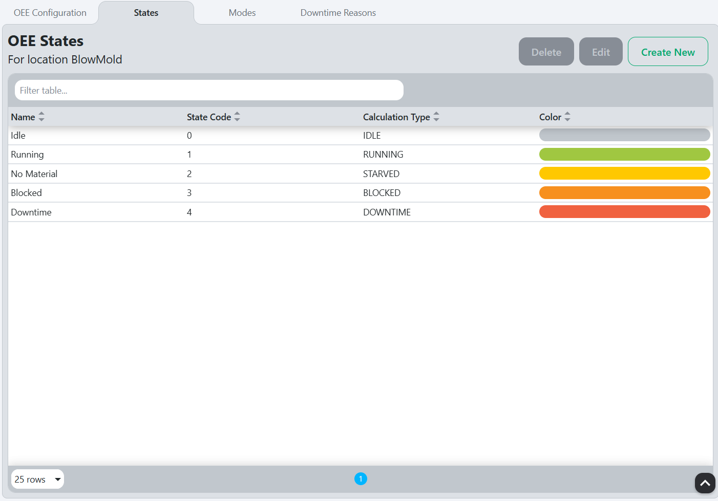
State Workflow
Create New State
- Click on the
Create Newbutton to create a new state. - Fill out the fields in the popup that appears (see Edit or Create New State Popup Fields for details).
- Click the
Confirmbutton to save the new state.
Edit State
- Select a state from the list on the left side of the screen.
- Click on the
Editbutton to open the edit popup. - Modify the fields in the popup as needed (see Edit or Create New State Popup Fields for details).
- Click the
Confirmbutton to save the changes.
State Fields
Delete
Deletes the selected state.
Edit
Opens the following popup to edit the selected state (in this case, "Downtime"):
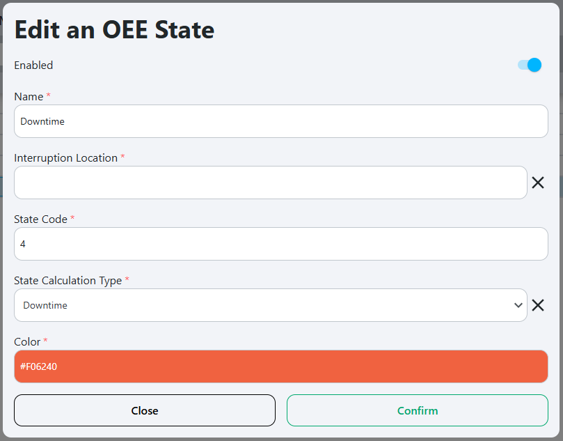
Refer to Edit or Create New State Popup Fields for details on the popup.
Create New
Opens the following popup to create a new state:
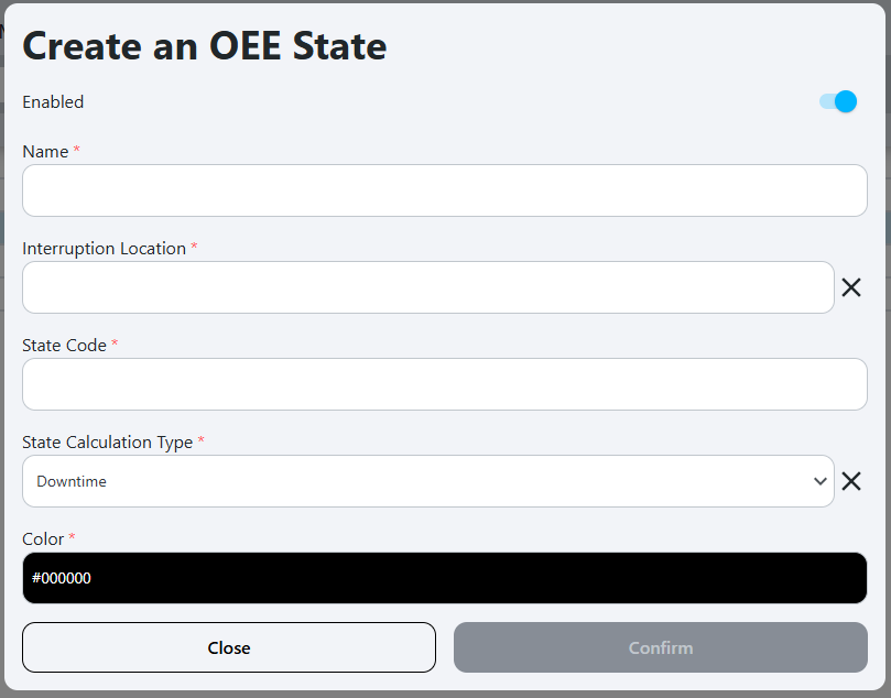
Refer to Edit or Create New State Popup Fields for details on the popup.
Edit or Create New State Popup Fields
Enabled
Toggles the state on or off.
Name
The name of the state. This should be a descriptive name that clearly indicates the purpose of the state (e.g., "Running", "Downtime", "Setup").
Interruption Location
This is a dropdown that allows the user to select an interruption location.
The interruption location is the location that is causing the state of the selected location to be set to the selected state.
Here are a few examples of states and their corresponding interruption locations:
-
State is
Downtime: The interruption location would be left blank, because downtime doesn't occur as a result of another location. -
State is
Starved: The interruption location would be the location that is directly before the selected location. This is because, for the location to be starved, the location before it in the production line must not be outputting what the selected location needs to run. -
State is
Blocked: The interruption location would be the location that is directly after the selected location. This is because, for the location to be blocked, the location after it in the production line must not be accepting an input from the selected location.
State Code
This is the integer code for the state, matching the PLC tag that indicates the state of the location. This code is used to identify the state in the PLC and should be unique for each state.
State Calculation Type
This is a dropdown that allows the user to select how the OEE record of the state will be handled. The options are:
- Idle: This is the default state for the OEE record, indicating that the location is not currently running or producing anything.
- Running: This is the state for the OEE record when the location is actively producing items. This state is counted towards the OEE calculation as running time.
- Downtime: This is the state for the OEE record when the location is not producing items due to a planned or unplanned downtime event.
- Starved: This is the state for the OEE record when the location is not producing items because it is waiting for input from a previous location in the production line.
- Blocked: This is the state for the OEE record when the location is not producing items because it is waiting for output to be accepted by a subsequent location in the production line.
Color
The color associated with the state, used for visual representation in the OEE timeline.
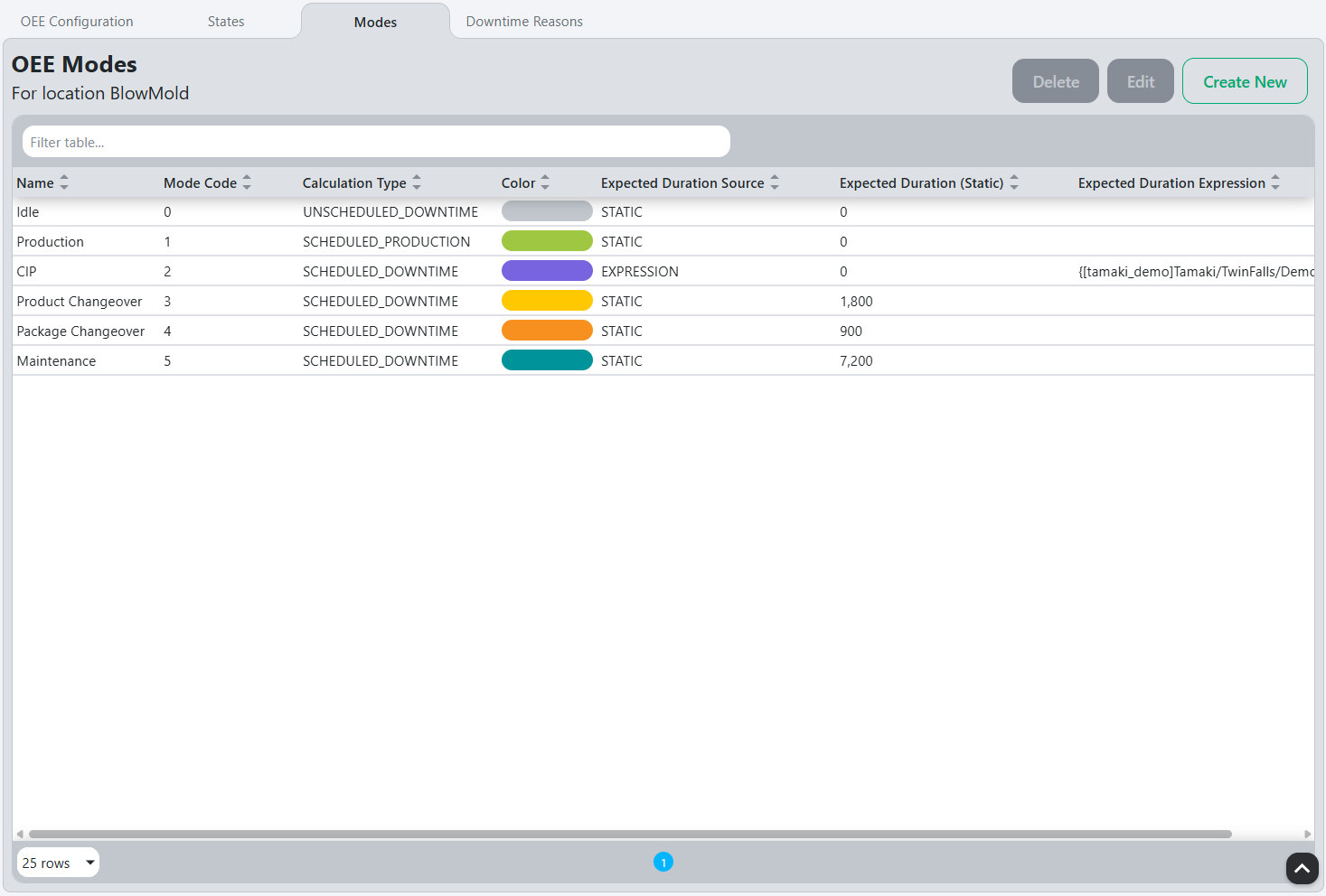
Modes
Example:
Mode Workflow
Create New Mode
- Click on the
Create Newbutton to create a new mode. - Fill out the fields in the popup that appears (see Edit or Create New Mode Popup Fields for details).
- Click the
Confirmbutton to save the new mode.
Edit Mode
- Select a mode from the list on the left side of the screen.
- Click on the
Editbutton to open the edit popup. - Modify the fields in the popup as needed (see Edit or Create New Mode Popup Fields for details).
- Click the
Confirmbutton to save the changes.
Mode Fields
Delete
Deletes the selected mode.
Edit
Opens the following popup to edit the selected mode (in this case, "CIP"):

Refer to Edit or Create New Mode Popup Fields for details on the popup.
Create New
Opens the following popup to create a new mode:
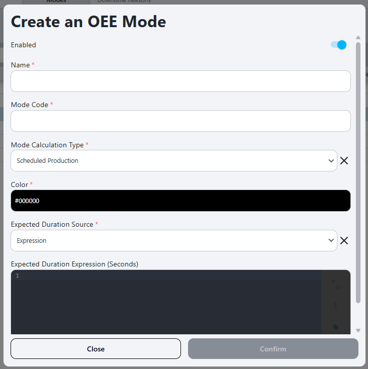
Refer to Edit or Create New Mode Popup Fields for details on the popup.
Edit or Create New Mode Popup Fields
Name
The name of the mode. This should be a descriptive name that clearly indicates the purpose of the mode (e.g. Idle, Production, Product Changover, Maintenance).
Mode Code
The integer code for the mode, matching the PLC tag that indicates the mode of the location. This code is used to identify the mode in the PLC and should be unique for each mode.
Mode Calculation Type
This is a dropdown that allows the user to select how the OEE record of the mode will be handled. The options are:
- Schedule Production: This mode is used for scheduled production runs, where the location is expected to produce items according to a predefined schedule.
- Scheduled Downtime: This mode is used for planned downtime events, such as maintenance or setup changes, where the location is not expected to produce items.
- Unscheduled Downtime: This mode is used for when the location is not planned to be producing items but not due to a planned downtime event. This could be simply idle time between production runs.
Color
The color associated with the mode, used for visual representation.
Expected Duration Source
Opens a dropdown with the following options:
- Expression: The expected duration will be determined by the Expected Duration Expression field.
- Static: The expected duration will be a fixed value set in the Expected Duration field.
Expected Duration Expression (Seconds)
The Expression Field where the PLC tag for the expected duration of the mode is bound to the OEE model. This allows for dynamic calculation of the expected duration based on real-time data.
Expected Duration (Seconds)
The fixed value for the expected duration of the mode, defined in seconds. This is used to set a baseline for how long the mode is expected to last, which can be useful for planning and scheduling purposes.
Downtime Reasons
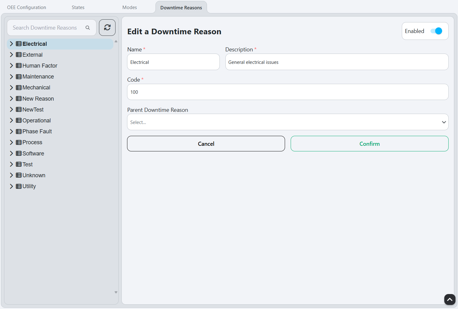
Example:
Downtime Reasons Model oee downtime reason
Downtime Reasons Workflow
Create New Downtime Reason
- Right-click either on empty space in the tree, or on the downtime reason which you want to use as the parent reason.
- Click
Add Downtime Reasonin the context menu that appears from right-clicking. This will populate the right side of the screen with empty values, and set the Parent Downtime Reason to what was right-clicked (see Edit or Create New Downtime Reason Fields). - Fill out the fields on the right side of the screen (see Edit or Create New Downtime Reason Fields for details).
- Click the
Confirmbutton to save the new downtime reason.
Edit Downtime Reason
- Select a downtime reason from the tree on the left side of the screen. The right side of the screen will be populated with the details of the selected downtime reason.
- Modify the fields on the right side of the screen as needed (see Edit or Create New Downtime Reason Fields for details).
- Click the
Confirmbutton to save the changes.
Downtime Reasons Fields
Downtime Reason Tree
The downtime reason tree displays the hierarchy of downtime reasons. It allows users to navigate through the downtime reasons, making it easier to add or edit a downtime reason.
To edit a downtime reason, select it from the tree to populate the right side of the screen. See Edit or Create New Downtime Reason Fields for details on the fields.
To create a new downtime reason,
Edit or Create New Downtime Reason Fields
Name
The name of the downtime reason, which is displayed in Downtime Entry and other places in the MES. This should be a descriptive name that clearly indicates the cause of the downtime.
Description
A concise, detailed description of the downtime reason, providing additional context and information about the cause of the downtime. This can help operators and managers understand the issue better and take appropriate actions.
Code
The integer code for the downtime reason, matching the PLC tag that indicates the downtime reason or fault code of the location. This code is used to identify the downtime reason in the PLC and should be unique for each downtime reason.
Parent Downtime Reason
The parent downtime reason, which is used to create a hierarchy of downtime reasons. This allows for categorization and grouping of related downtime reasons, making it easier to analyze and report on downtime events.